Search the Community
Showing results for tags '2 - intermediate'.
-
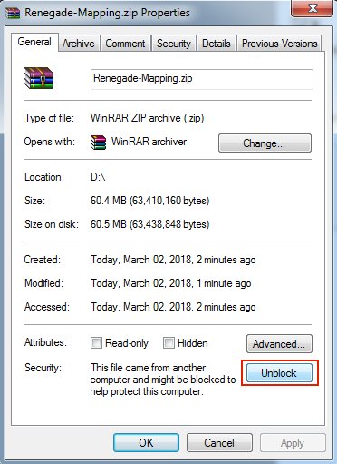
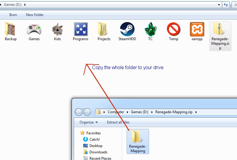
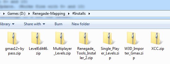
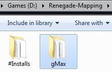
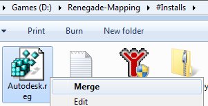
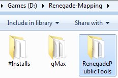
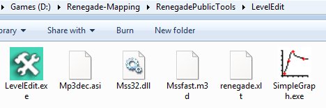
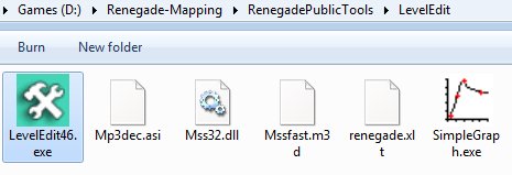
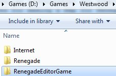
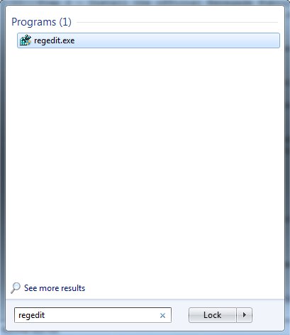
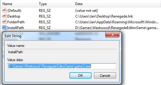
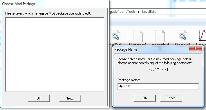
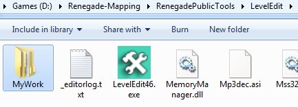
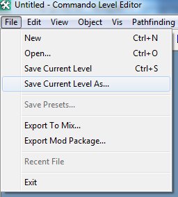
The Environment Setup Tutorial This tutorial will attempt to learn you how to setup your entire working environment for creating maps in gMax and the free provided Renegade Public Tools v2. It includes all the tools you need and they should be installed in this particular order: 1- The gMax Installation Files and Registration ByPass. (NOTE: Windows 8+ and 10 are NOT supported, you'll need Windows 7 or XP Pro to use gMax without glitches, there is NO fix for this.) 2- The official Renegade Public Tools version 2 from Westwood Studios. (Works fine with 8+ and 10) 3- The unofficial LevelEditor from Tiberian Technologies for support with 4.6 Scripts Update. (Works fine with 8+ and 10) 4- Some (semi) Critical Assets required for making a map for Renegade in gMax/RenX. 5- The XCC mixer i personally have been using since i don't know when, it's the best eventhough it's not the latest. Environment Guide Package Download the file i prepared as zip from the MPF download area: Once it is downloaded, make sure you unblock the file by going to the zip properties and clicking "Unblock" BEFORE you extract it. In this tutorial i will install EVERYTHING to do with mapping for Renegade in my folder on the D drive in "Renegade-Mapping". Go ahead and extract the zip somewhere, open it in a new window: And then copy the contents somewhere: Go into the #Installs folder that you extracted inside the Renegade-Mapping folder Step 1 - Install gMax and apply the registry fix We need to install gMax first, you MUST install it first or it won't work properly later. Open the gmax12+bypass.zip and copy files into your #Installs folder and then run gmax12.exe to install it. In this guide i am installing directly into the Renegade-Mapping folder so the endresult will be something like the following: Now, because the author of gMax doesn't send out emails anymore to register gMax for free, there is included a Autodesk.reg file, right click on that and choose Merge and when promted do Yes to merge it. When installation is done and you merged the registry thing, then run gMax for the first time. You will be prompted to select a rendering device, here you choose "Direct 3D" and continue. Once it has fully loaded you must exit gMax again. Step 2 - Install the official Renegade Public Tools v2 Extract the file Renegade_Tools_Installer_2.zip and run the executable, install it into your Renegade-Mapping folder, endresult should look simular to this: Go into the folder LevelEdit and you will see these files: Now delete (yes delete permanently) the LevelEdit.exe that is currently there, the original from Westwood. Extract the file LevelEdit46.zip and copy the resulting LevelEdit46.exe to your LevelEdit folder like so: Goto your Renegade GAME folder, which you updated to the latest TT Script Update (available on http://www.tiberiantechnologies.org ) Copy the following files to your LevelEdit folder and overwrite any existing ones there: "MemoryManager.dll" "Mss32.dll" "Shared.dll" "ttle.dll" You should end up with a LevelEdit folder looking like this: Now make a complete copy of your Renegade game folder (which is updated to 4.6 of course) and name it "RenegadeEditorGame", just copy and paste it somewhere like: Now open the Registry Editor through your startmenu "search" option type: regedit and open it. Expand the folders (or keys as they are called) until you are inside the Renegade folder/key. "HKEY_LOCAL_MACHINE -> SOFTWARE -> Wow6432Node -> Westwood -> Renegade" You see the InstallPath option there? Double click on it and change its value to where your game2.exe is located in the RenegadeEditorGame you copied earlier, in my example here it would be: D:\Games\Westwood\RenegadeEditorGame\game2.exe Now close the Registry Editor program, we don't need it no more now, you don't need to save anything, it does so automatically. Run the Editor Ok, so we can finally run the editor now, go into the LevelEdit folder and run LevelEdit46.exe There click the "New..." button and call it for example "MyWork". Double click the MyWork in the window and it shall bring up the editor in action: You'll notice the editor created a folder called "MyWork": Which contains a few key folders the editor uses: Create a map project folder inside the levels folder like so: Inside this folder you will save your Editor's "C&C_My_Map.lvl" file and stuff related to your map such as W3D models/terrain and maybe textures, cinematic text files and/or audio. ALWAYS choose to "Save Current Level As..." inside the editor ALWAYS WHENEVER you want to save your progress, do NOT EVER use "Save Current Level" (trust me), period, or it will not update some files (lsd/ldd/ddb) for your map and it wont work properly when you make a .mix with XCC later on. For example the endresult could look like this: << i will update this guide later tonight or tomorrow, just 1 thing: If you have missing textures make sure you place them in your Editor_Cache folder and reload the editor >>
-
Hi! This is the testmap i wipped up with a tiberuim field and a Weapons Factory + Refinery. We will setup the WF first, then the Refinery and their waypaths and finally the Tiberium Field itself. I did not include the airstrip here as the procedure is the same for that one, except that the Carmaker thing should face along the path of the airplane that drops the vehicles. First we create the Building Controller for the Weapons Factory, you can find it under 1)Buildings, then 2)WarFactory and select 3)mp_GDI_War_Factory now click on the 4)make button at the bottom right. Select the blue icon controller and position it like on the image below: First press Ctrl+Shift+T to hide the doors from the Weapons Factory which allows us to do the next step: Select the Blue House building controller again and press Ctrl+P, a red Car will appear on the map with a blue line connecting it to the controller. Position this red Car inside the Weapons Factory construction bay around the center of it like on my image below: Next we need a vehicle construction zone around the Car completely encompassing the construction bay. Goto: 1)Object, 2)Script Zone, 3)CnC and select 4)Vehicle_Construction and 5)make it on your map. An orange box appears, position it inside the construction bay and drag it around the whole floor, make sure the Car is completely covered inside it. To make the zone larger upwards hold your shift key and drag one of the black boxes on the edges up or down. Good luck: Now we need to cover up the space or gaps in the WF vehicle dropoff bay in front of the WF door. This is required otherwise the AI does not drive out of the WF and your vehicles will stick in the WF construction zone which is bad. So in the editor goto: 1)Editor Objects, 2)Editor Only Objects and select 3)Large_Pathfind_Blocker and 4)Make it on your map. A green box with 'large dsapo' written on it appears, on the Z axis move it down under the ground until all you can see is the top of the box. To make a quick copy of the box left click on the box and hold your mouse button, then simultaniously rightclick once: it creates another box, yay. Position lots of them covering the gaps in the WF delivery pad as on the image below: Ok so now the waypaths. First click the toolbar red cone icon (position at cursor it is called) on the screenshot at number 1 position. Now goto the presetlist and goto 2)Waypath and select 3)Vehicle Only Waypath as shown on the screenshot below: Now click MAKE to make your first waypoint on the map. Position it at the left side in front of the Car INSIDE the construction zone and left click to place it. Then you can position the second waypoint, put it in the center area of the pad and leftclick to place it, then the last point you position just off of the pad, left click to place it, then press the escape key to exit waypath mode. You should end up with something like this: Now left-double-click on one of the way POINTS, not the WayPATH, and in the box that appears goto the Waypath tab and make sure the options 'Two Way', 'Ground Vehicle' and 'Innate Pathfind' are checked like on the screenshot below: Repeat the above until you have 3 waypaths coming out of the WF construction zone, like seen on screenshot below: Now we need to place a pathfind generator here. Goto 1)Editor Objects, 2)Pathind Generator and click on 3)Human and 4)Make it on your map. Position it near the waypaths as seen on the screenie below: Now goto the Refinery on your map and make the building controller there (Buildings->Refinery->mp_GDI_Refinery) Select it and press Ctrl+P to create the red Car for this building too. Position it like on the screenshot below: Now create a Vehicle Only Waypath from the Car to the center of the Tiberium Field. Left click to place a point, place as many points as you want. To finalize the waypath you press escape. PS: You can move around in the editor using the numpad numbers on your keyboard while in waypath mode. Double leftclick on a wayPOINT and set the options as seen on the screenshot below: Do the same with the MIDDLE waypath from the WF to the Tibfield like on the screenshot below: Now we need to place the tiberium field zone for the ai harvesters. Goto 1)Object then 2)Script Zone then 3)CnC then 4)Tiberium_Field then select 5)Tiberium_Field_GDI (or _Nod if you are working on the Nod tibfield) and 6)Make it. Position it over the tiberium field and make sure that the last waypoints of the waypaths from wf and ref are inside it. Make sure you save your map AS, then goto Pathfinding->Generate Sectors Now save your map again when thats done, make a mix file and host a 1p LAN game to test it, it should create the harvester and drive to tiberium then dump at the refinery. Greetz zunnie
-
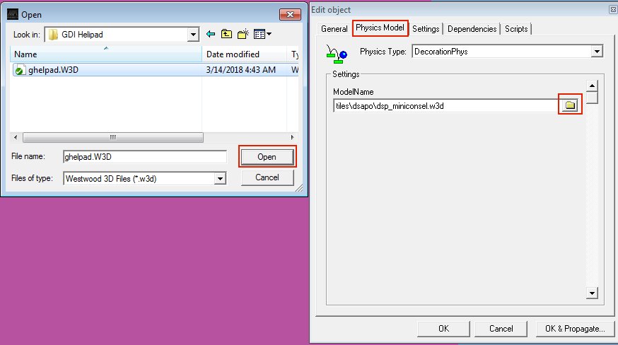
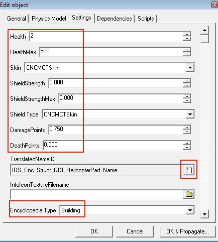
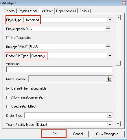
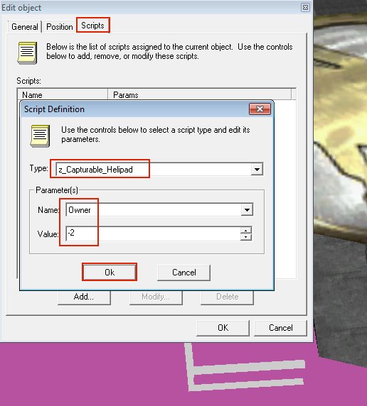
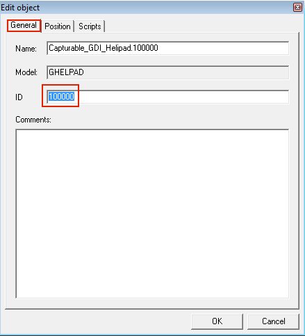
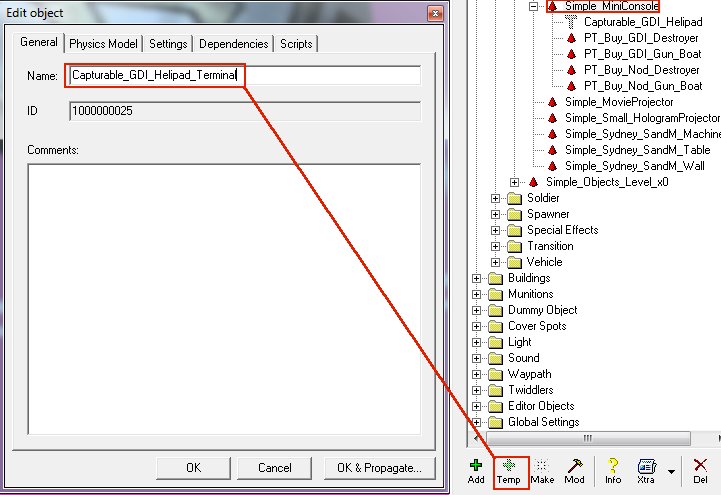
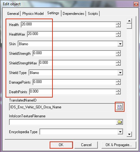
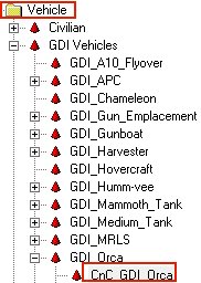
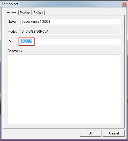
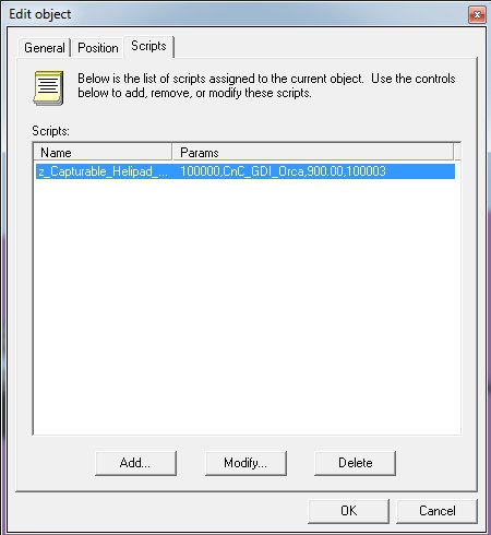
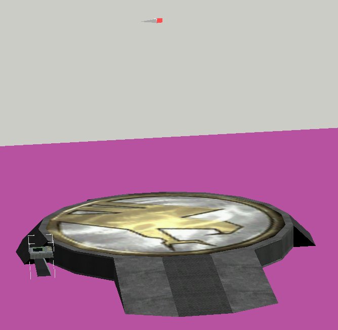
The Helipad models and textures are in zip: CapturableHelipads.zip Temp Object->Simple->Simple_DSAPO_Versions->Simple_MiniConsole and name it Capturable_GDI_Helipad On the Physics Model tab browse for the model by clicking the folder icon and choose Open On the Settings tab set Health to 2 and HealthMax to 500, Skin and ShieldType both to CNCMCTSkin with a DamagePoints of 0.750 and DeathPoints 0.000 Click the Letter icon to choose the Helipad name from the category Enc and set Encyclopedia Type to Building Still on the Settings tab set PlayerType to Unteamed and Radar Blip Type to Stationary Now MAKE your Helipad on the map Goto the Scripts tab for the properties of the Helipad and select Type: z_Capturable_Helipad and set the Name Parameter of Owner to -2 Now note the ID of the Helipad in a textfile for later use: Now TEMP the Simple_MiniConsole and name it Capturable_GDI_Helipad_Terminal On the Settings tab for the Terminal set the Skin and Shield Type to Blamo and Damage and Deathpoints to 0.000 We want this Terminal to grant a Orca so we click the Letter icon and choose the Orca name from Enc category: Make note of the GDI Orca exact multiplayer presetname, in our case this would be the original preset aka CnC_GDI_Orca (case sensitive): Next we MAKE and position a Daves Arrow on TOP of the Helipad and move it UP on the Z-axis until it floats like 3 orca's high in the air above the Helipad like so: Note the ID of this Arrow (PS: Do NOT delete the arrow, you must leave it on the map) Go back to the Helipad Terminal on the map and goto its properties and the Scripts Tab, add the following script to it "z_Capturable_Helipad_Terminal" with the settings as displayed below. HelipadID would be the ID of the Helipad on the map we created first, in this example ID number 100000 Preset would be the vehicle to create at the location of the Daves Arrow we placed so CnC_GDI_Orca and 100003 An Orca costs $900 in Renegade so we enter that as the Cost for it. Endresult should look like this for the Helipad Terminal: You're done:
- 2 replies
-
- renhelp.net
- zunnie
-
(and 5 more)
Tagged with:
-
- 1 reply
-
- 3dsmax
- w3d viewer
-
(and 3 more)
Tagged with:
-
You will want to download http://multiplayerforums.com/index.php?/files/file/624-maulers-renegade-sidebar/ for this tutorial. Now that scripts 4.1 allows you to use the sidebar stand-alone in a Renegade map, its time to write a tutorial for how its done. The first thing you need to create are textures for the sidebar. [iNCLUDED IN THE DOWNLOAD LINK] You need to create a top half texture, bottom half texture and up and down arrow textures. They can be the same for both teams or different for each team. Then, you need to create an ini file. If your map is named C&C_MyMap, the ini file should be named C&C_MyMap_tt.ini In this file put something like this [General]AlternateSelectEnabled=falseNewUnpurchaseableLogic=falseVehicleBuildingDisable=falseGDIUpArrowTexture=up.tgaGDIDownArrowTexture=down.tgaGDIBackgroundTexture1=gdisidebar_mau.tgaNODUpArrowTexture=up.tgaNODDownArrowTexture=down.tgaNODBackgroundTexture1=nodsidebar_mau.tgaSidebar=true Obviously the names of the textures should match the names you gave them when you created them. You can also optionally add SidebarSoundsEnabled=trueSidebarRefillSound=xyzSidebarInfantrySound=xyzSidebarVehicleSound=xyzif you want sounds to play when sidebar items are purchased.The sounds need to be 2D sound presets created in LE. (obviously replace xyz with the name of the sound to use). The sounds are played whenever something is purchased (i.e. double click etc) Note that the sidebar does not display any text on top of the icons except for the cost so you will need to either rely just on the pictures or you will need to add text to your icons. Also note that all players using your map will require scripts 4.1 (as will the server) in order for this to work. Also, the sidebar does not allow you to purchase beacons (unlike the PTs) so if you want beacons to be purchasable, you will have to add separate terminals to let you do that (there are plenty of scripts to make that happen) ok, time for part 2 of the tutorial (which is necessary if you want objects to disappear when the building that normally builds them goes away) First, in the C&C_MyMap_tt.ini file (or whatever), put this line at the end after the others NewTechLevel=trueThen in leveledit, go to Global Settings then Purchase Settings. For each of Character Classes (GDI), Character Classes (Nod), Character Classes (Secret GDI), Character Classes (Secret Nod), Vehicles (GDI), Vehicles (Nod), Vehicles (Secret GDI) and Vehicles (Secret Nod), create a temp preset copy (or if you already have one, edit it). What you need to change is the Factory Building Type for each entry. For soldiers, set it to Soldier Factory. For vehicles, set it to Vehicle Factory. If you are using my helipad tutorial (to be posted shortly) set helicopters/air units to Helipad.If there are units you dont want on the sidebar (e.g. the secret hidden extra vehicles), set their object to none. The usual enable/disable for extras (EXTRAS console command etc) will not work with the sidebar. That should be all you need to do, no extra scripts are required, the engine logic behind NewTechLevel=true will do all the work of making the items vanish from the sidebar when the relavent building is destroyed.
-
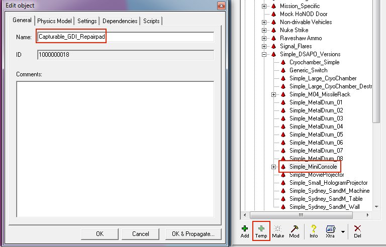
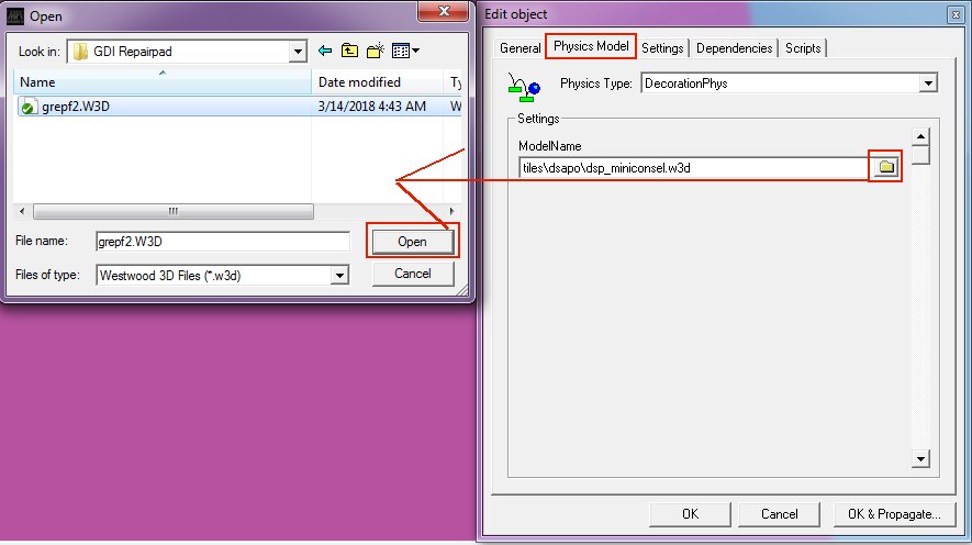
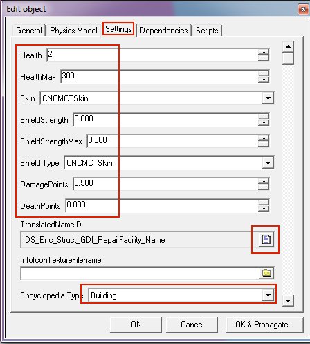
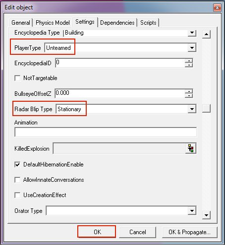
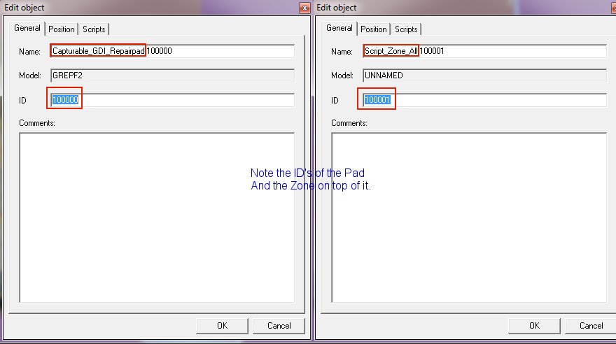
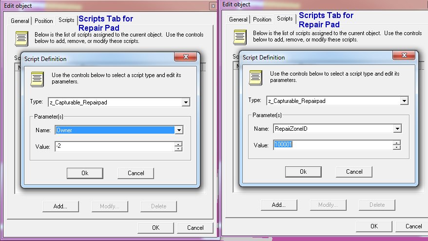
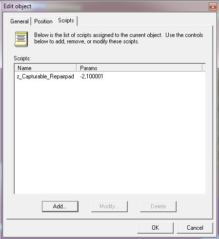
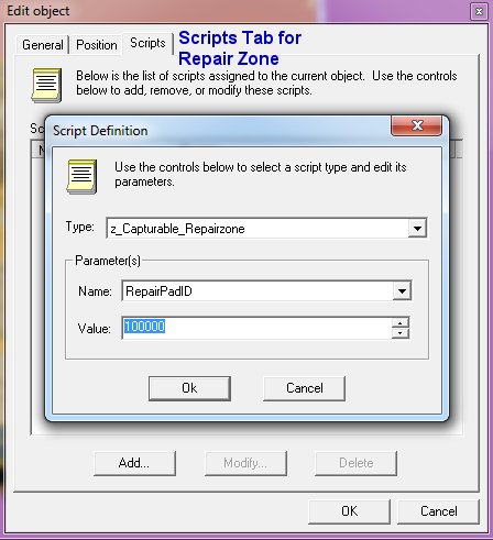
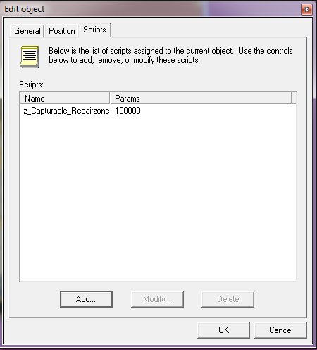
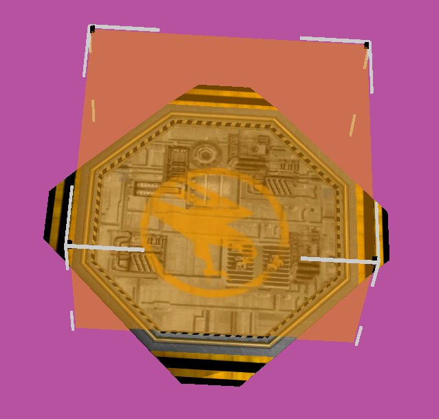
The Repair Pad models and its textures you are gonna need are in the zip: CapturableRepairpads.zip Temp it under Object->Simple->Simple_DSAPO_Versions->Simple_MiniConsole and name it "Capturable_GDI_Repairpad": On the Physics tab browse for the model by clicking the folder icon and open it: Give it 2 Health, 300 MaxHealth (Shield & ShieldMax should be 0.000) Give it CNCMCTSkin as Skin and Shield Type (even if its set to 0.000) Click the letter icon for TranslatedNameID and go into the Enc category and find the RepairFacility one as shown below Make the Encyclopedia Type a Building Still on the Settings tab set PlayerType to Unteamed and Radar Blip Type to Stationary Now you can "MAKE" it on your map: Next goto Object->Script Zone->Script_Zone_All and MAKE it, position it on top of the repairpad as seen on the image below. To make it higher in length hold down SHIFT and then move your mouse up/down by selecting the black little boxes of the zone. Now get to the properties of the Repairpad and note its ID, in this example 100000 Get to the zone properties too and get its ID, in this case 100001 Goto the properties of the Repair Pad and its Scripts Tab, there you add the script z_Capturable_Repairpad with the Name parameter of Owner set to -2 (unteamed) Set the Name parameter RepairZoneID to the ID of the Zone you noted in the step earlier, which in this example is 100001 Endresult should look like this for the repair pad: Now edit the Script_Zone_All that you placed on top of your Repairpad by going to its properties and on the scripts tab add the script "z_Capturable_Repairzone" and set the Name parameter for RepairPadID to the ID you noted earlier for the Repairpad, in this example it is 100000 Endresult for the zone should look simular to this: Now save your level and you will have a capturable repair pad on your map! Repeat the above process for Nod but then with the Nod model of course.
-
This tutorial shows how to set up a custom lift C&C Renegade. Part 1: http://www.youtube.com/watch?v=WQ7-hgHXZ5s Part 2: http://www.youtube.com/watch?v=-qH7e9kYEqo Part 3: (demo) http://www.youtube.com/watch?v=CcOEI_BIGZg
-
These files you need for the Recon Bikes: ReconBikeFiles.zip This tutorial will cover setting up the Recon bikes entirely for both Nod and GDI. We will modify the weapon, the weapon ammo, the bike settings themselves and add them to the purchase terminal options. The settings i use make the Recon bike well worth its $700 imho, in most maps its a piece of shit lol. With the settings used here you make it a valuable asset for the teams although they do still die very fast. The reason i gave it 10 armor points is because it then takes 2 ramjet shots extra to kill it. Ok let's get on with the show. I am assuming you have already loaded the terrain for your map and are now ready to setup the Ammo for the Recon bikes. 1) Setup the AMMO Expand 1)Munitions, then 2)Ammo, then 3)Ammo_Vehicle_Weapons and click on Ammo_ReconBike_Rocket_Player. While selected click on the 4)Temp button Give the ammo a name such as Ammo_Recon_Bike Goto the Settings tab and change the following settings accordingly and then press OK to temp the new ammo preset: EffectiveRange: 135.000 Velocity: 80.000 RateOfFire: 50.000 You should end up with something like this in the preset listing after pressing OK to Temp it: 2) Setup the WEAPON Now Expand 1)Munitions, then 2)Weapons, then 3)Weapons_Vehicles and select the Weapon_Reconbike_Player. While selected click on the 4)Temp button Give it a name, such as Weapon_Reconbike_Good, then proceed to the Settings tab and enter the following settings: SwitchTime: 0.500 ReloadTime: 1.000 KeyNumber: 0.000 Scroll further down to the options for PrimaryAmmoDefID and SecondaryAmmoDefID and click on the 1)button to change the Ammo it uses to Ammo_Recon_Bike (what we temped under Ammo in Step 1) as shown on the picture below: Endresult should look like this: 3) Setup the Nod Recon Bike Expand 1)Object, then 2)Vehicle, then 3)Nod Vehicles, then 4)Nod_Recon_Bike and 5)select CnC_Nod_Recon_Bike and finally click 6)Temp Enter a name like Nod_Recon_Bike_Good, goto its Settings tab and set the following options: Health,HealthMax: 225.000 ShieldStrength,ShieldStrenghtMax: 10.000 Shield Type: CNCVehicleHeavy DamagePoints: 0.070 DeathPoints: 50.000 Scroll down to the WeaponDefID setting and click the button and change it to the temp we made earlier: Endresult should look like this: 4) Setup the GDI Recon Bike Select the temped Nod_Recon_Bike_Good we created in the previous step, and click on the Temp button, name it GDI_Recon_Bike_Good like on the image below: Goto the Physics Model tab and under Settings ModelName click the folder icon and browse for your v_gdi_bike.w3d Goto the Settings tab and set PlayerType to GDI: 5) Add to Purchase Terminal Options for GDI Under Global Settings, Purchase Settings select Vehicles (GDI) and TEMP it, name it Vehs GDI: Goto the Settings tab and scroll all the way down to Entry 10, for Name click on the letter-icon, Goto the Tab "ENC" and scroll down to the Reconbike name as on the image below and select it: For Cost we do 700, the Texture we set to hud_gdirecon.tga and we select the GDI_Recon_Bike_Good for the Object: Endresult looks like this: 6) Add to Purchase Terminal Options for Nod Repeat Step 5 above but this time select the Vehicles (NOD) and Temp it and name it Vehs NOD Goto Entry 10 and set the letter-icon to the reconbike name, cost 700. Take note that you set the Texture for Nod to hud_reconnod.tga and for the Object you select the Nod_Recon_Bike_Good. 7) All done! If you did this correct and make your mix file (make sure you include the w3d and dds and tga files in it) you SHOULD be able to buy Recon Bikes. Good luck!
-
City/Square Tunnel Tutorial By Pwn Call (aka ESCALADE) ---------------------------------------------------- This tutorial is for making basic square or really basic shaped tunnels , just not including cave/rock type uneven tunnels although some of the same basic principals can be used for those type of tunnels as well. When you are done they could look something like this ------------------------ First I will do a small intro about the Snap to Grid tool, which in my opinion is the most useful function when making maps, that I just recently found out about. In the lower right corner of your RenX screen there is an area for Snap to Grid as well as a few other options, another really useful tool is the Snap Rotate tool which snaps to increments of 5 degrees by default. Look in the image below and the lower left icon with the magnet and the 3 is the Snap to Grid tool. It is default set to off so left click to turn it on. You will know your Grid is on when you see the cyan + sign displayed on the grid. To change the increments of the snap to grid or snap to rotation simply right click on them and a menu will pop up, go to the Home Grid tab and then change the grid spacing to your desired ammount, for this tutorial start the grid at .25. If your tunnel is significantly bigger, (for tanks for example) you can have the grid much larger like 1. Ok first you need to start off in Gmax with an area that your tunnel will be cutting through, could be a mountain or building but generally it should have a flat surface at the entrance and exit because it will make it easier to make. I recommend using the Grid throughout the whole thing as it makes it much easier. First this is my block I will put my tunnel through Now you need to create your tunnel. I have my view on the Left for this tunnel and simply make your box the size you want your tunnel, also note that you want some extra room on the sides and top because the dimensions of this box will be for the outside of your tunnel not the inside which you will see in a moment. Notice the blue line is the object I'm cutting through and the white is the new box that will be my tunnel. Also make sure that it is long enough to go all the way through your object so you can change the length or in my case since I made my tunnel from the side view the height. Next what you will do is create another box that will cut out your tunnel. This box needs to be smaller than your first box on the sides and top but make sure it goes down below the bottom like in this next picture. This will be cut away from your original box leaving your tunnel to walk through, here you can change the width of your tunnel sides and ceiling by making this box smaller or larger. Next change to the Top view again and make sure that the box goes all the way out past your original tunnel box so it cuts all the way through. If it isn't long enough change the length or height to make it long enough. It should look something like this. Here is the same thing in the perspective view Next what we will do is customize our user interface to add the boolean tool to the toolbar which is useful for tunnels and other objects. Go to customize then user interface Then go to the toolbars tab and scroll down to boolean compound object Once you find it click and drag it up onto your toolbar, it doesn't have to be where I put it just somewhere for easy access. Now we will select our original tunnel box mine is the outlined box in this picture Then we click on our new boolean tool icon This will open up the bar on the side for the boolean tool options. I will explain the other ones at the end of this tutorial but for now it should be set on Move and the choose Pick operand B So now while using the boolean tool after you hit pick operand B the next object you click on will be removed from the original object. So now click on the box that you want to remove from your tunnel and POOOF!! its gone and it took away from the other box and leaves you with a tunnel type object! If you accidentally pick on the wrong object no worry just hit undo and then select again. After you use the boolean tool on an object always turn it into an editable mesh afterwords, this way you can edit it or take another boolean out of it if you wish. Do this by right clicking on the object then Convert to Editable mesh Side note for boolean tool, NOT NECESSARY FOR TUNNEL TUT (So if you want to use boolean to make windows in a wall for example you would do your first boolean then convert to editable mesh, then select boolean again for the next window then turn into editable mesh, and keep repeating this process for all of your items that are taking away from the original object.) Now notice it did not cut away from the building that the tunnel is going through, this is because only the tunnel was selected when doing the boolean tool. Now we will cut through this box as well so we can go through our tunnel. So now change your grid spacing to half the size of what it previously was so in my case I will change it to .125 now. Now we will make a box that will cut out of the building, your settings might be messed up from using the boolean tool so go to the create tab and then standard primitives to make another box Make your next box in between the inside and outside of the tunnel and below the bottom. If it is inline with the inside edge of the tunnel then two textures will be in the same area and it will flash in between the two textures and look weird on your map. Again make sure it goes out past the length of the tunnel so it cuts through all the way so make it bigger like in the second image here Now select the building that your tunnel will go through, in my scene the blue square. Now go to the boolean tool And again move should be checked and the pick operand B Then click on the part to take out, again in my case the green square. And there your tunnel should work now! And don't forget to turn the building back into an editable mesh! Alright this is where the basic tunnel is finished, if you want your entire tunnel to be the same texture just add the texture you want to it and create a plane for the floor. If you want different textures for the walls and ceiling then do not add a texture to it and continue reading below. ----------------------------------------------------- Advanced Tunnel Textures. If you want the sides of the tunnel, the roof of the tunnel and the outside of the tunnel to be different textures then follow these steps! Before you start this make sure there are no textures applied to your tunnel at all first, otherwise it could mess things up and will be harder to add the textures to different parts of your tunnel. Your tunnel should be an editable mesh, if it isn't right click on it and turn it to an editable mesh. Then under the modify tab on the right click on editable mesh and then the polygon icon Next where it says Perspective in the upper left part of the Grid, right click on it and turn on edged faces if they weren't on. This helps you see which parts of the tunnel you have selected. Now that you can see better what you are selecting select both of the walls of the tunnel like in this picture, see how they are outlined in red now. Now right click on the selected area and go over to detach and click it. A smaller window will pop up if you want to name it something different than what is in the blank you can but it is not necessary. Neither box should be checked and hit ok to detach it. Now do the same thing for the ceiling, select it and then detach it. Now you should have 3 separate meshes for your tunnel, be careful because they can be moved separately now as well. Texture each of them differently to make your tunnels look more realistic like the ones I show below. A good idea once you texture them is to group them by selecting them all and then go to to group menu and then group. This way you can clone them and move them to other places if you wish. You can also change the shapes of your tunnels by converting them to editable mesh and then moving one end to make them go up or down. Play around with it a little bit and you can do some pretty neat things with the boolean tool. If you have any questions post them up and I'll do my best to answer them!
-

2 - intermediate [VIDEO] Creating Alpha Channels and Materials
Guest posted a topic in Skins And Textures
- 6 replies
-
- photoshop cs6
- 3dsmax 8
-
(and 3 more)
Tagged with:
-
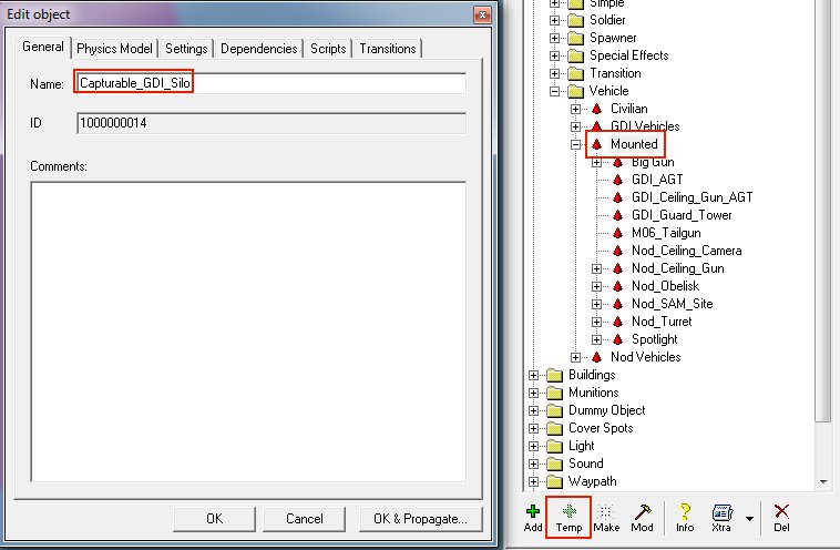
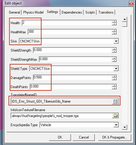
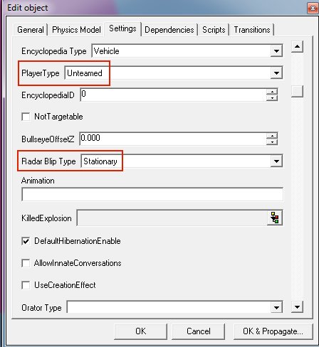
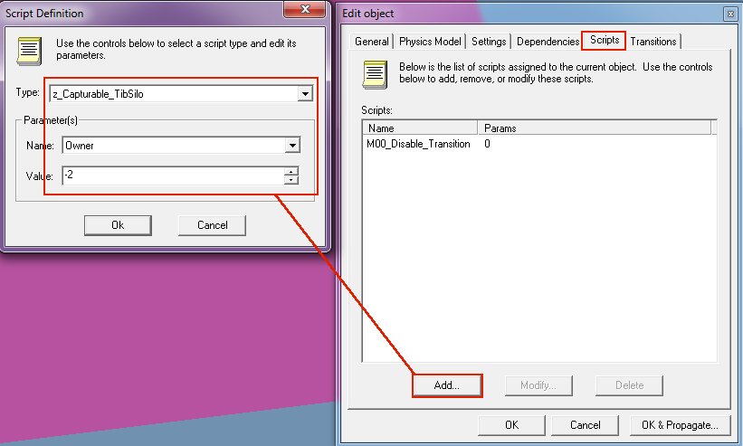
Required Files: CapturableTiberiumSilos.zip TEMP a preset into Object->Vehicle->Mounted and call it for example "Capturable_GDI_Silo": Goto the Physics Model tab and for ModelName click the folder button and browse for the gtsilo.W3D file, click Open: Goto the Settings tab and set Health to 2 and Healthmax to 300 (yes: ShieldStrength and Max should be 0.000) Set Skin to CNCMCTSkin and Shield Type to CNCMCTSkin Set DamagePoints to 0.500 and Deathpoints to 0.000 Set the TranslatedNameID to IDC_Enc_Struct_GDI_TiberiumSilo_Name (found in the strings editor under the Enc category) Still on the Settings tab set PlayerType to Unteamed Radar Blip Type should be Stationary Goto the Scripts tab and click Add... for Type browse for the z_Capturable_TibSilo For Name parameter Owner we set the Value to -2 (which means unteamed). Now select your temped preset called Capturable_GDI_Silo and click on "Make" button. It will appear on your map. Save your level and make your mix file. Now people can play your map and capture the silo. Repeat the above process for the Nod Tiberium Silo but set Team to Nod, that's all. Greetz zunnie
-

2 - intermediate Creating Emitters (Particle Effects) - Author: Genocide
Guest posted a topic in Miscellaneous
Basic Emitter Tutorial by Genocide Emitters serve purposes such as the smoke trail for the Rocket Launcher and Tiberium Dust Creating a successful emitter is easier than you would of think, all you need is the Renegade Mod Tools which if you don’t have you can get here: http://multiplayerforums.com/index.php?/files/file/80-renegade-public-tools/ After you have got that, browse for the mod folder, which generally is: C:\Program Files\RenegadePublicTools\W3dView, after that you will see W3dview.exe, open that and you should see the following: After the program is open, select the Emitters tab located at the top menu then choose, Create Emitter, when that happens the following window will open where you will edit all your settings: Here you shall name you emitter anything you wish, I suggest if you are making a smoke Emitter you leave the Particle Lifetime to 1.000 Secs, for future reference, the longer the Lifetime the longer the Particle Trail. I have changed the Rendering Mode To: Quad Particles Now we are going to add a texture to the emitter, you can do so by going to browse and search for a .tga file extension file. (If you have a texture and want to convert it to a .tga file then download advanced paint programs such as “Jasc Paintshop Pro”, and “Adobe Photoshop”) After Selecting, the best shader for a light Smokey texture would be “Screen”, after selecting that the texture we need to move to the Emission Tab where we will change the Density of the Emitter this is what I have done by editing the Particles, Rate And Creation Volume : Now, Notice the more dense the emitter has got, now time to move to the Rotation tab, I have skipped a few tabs because they will not necessarily be needed when creating a smoke Emitter, here I have edited rotation to make the emitter look more realistic: Now we are finished with the Very Basics of creating an emitter , I suggest playing around with this program to find out just what amazing emitters you can make, even ones that have sound attached to them! , I hope I have entered you well into the world of emitter creation, after playing around some more here is my finalised smoke emitter : Thanks for reading my tutorial and I hope that you become a great emitter creator, Genocide. -
Tools used, 3DSMax 8, W3D Tools for 3DSMax8 Creator: Mauler Create a cone or cylinder. Apply the texture setting as follows, Vertex Material Tab Set Ambient,Diffuse,Specular to black and Emissive to whatever color you wish to emit - Apply Linear Offset with, UPerSec=0.02 VPerSec=0.03 Shader Tab - Blend Mode 'Add' Texture Tab - Stage 0 Texture I used Ref_Dust.tga for this Apply the texture to your cone and use your desired UV coordinates. Now apply a vertex paint modifier to your light mesh. Now select the bottom vertices of your light cone and apply the black vertex paint. This will help blend your edge and make it look like the light is fading out from its light source. Make sure the mesh has '2-Sided' applied under W3D Tab. There, once your done it will look like this.
-
Overview- Make sure you read the “How To Construct A Renegade Vehicle” document. - Vehicle behavior is defined by the model for the vehicle and properties assigned to the vehicle in the Renegade level editor - Your 3D model controls things like the number of wheels, which wheels steer and which wheels output torque. - The level editor is used to define things like how fast your vehicle drives, how much health it has, and how stiff its suspension is. - For this presentation I’ll take a model of a Ford Explorer that I downloaded off the internet and set it up as a Renegade vehicle. - Once you’ve modeled your vehicle (or downloaded off the internet like I did), you can start to prepare it for actual use in Renegade. - An easy way to get the necessary bones is to merge them into your model from the “VehicleSkel.Max” file. Setting up the wheels- Renegade will create physics wheels for your vehicle by searching for transform nodes (or bones as some people call them) which certain names. - The contact point of each wheel is defined by a bone whose name begins with “WheelP” - The center of rotation for each wheel is defined by a bone whose name begins with WheelC” - Refer to the “How To” doc for a full explanation of these bones and the available parameters. - Wheel meshes that are attached to the WheelC bones will rotation and move to follow the terrain in the game. - Once you have all of your wheels set up, you make sure that in the top viewport, the vehicle is centered about the origin and the front of the vehicle is facing down the X axis. If your vehicle has more than 4 wheels, then you should position it so that the centroid of the wheel positions is at the origin. (Yeah yeah, we really should to write a little maxscript to do this for you) Setting up the vehicle for collision- In all renegade models, the user has control over which meshes are used for various kinds of collision detection. This is done by using the W3D Tools utility in 3dsmax to set the collision options for each of your meshes. - For physical movement, all Renegade vehicles are a single box. This box is called the “WorldBox” and must be present in your vehicle for it to function properly. - When the vehicle moves in the world and when other vehicles and characters move into the vehicle, this box is used to resolve the collision. - For bullets and other effects, the actual meshes in the vehicle may be used for collision. Turret- Vehicles may have a single turret which is defined by a set of bones. - The “Turret” bone will be rotated about its Z axis as the user moves his targeting cursor left and right. - The “Barrel” bone will be rotated up and down as the user moves his targeting cursor up and down. - One or more muzzle bones will be used as the actual creation point for the vehicle weapon’s projectile. - See the “How To” doc for an explanation of these bones Exporting your vehicle- Your vehicle should be exported with its wheels in their extreme highest position. - In this position, all of the contact points for your wheels (the WheelP bones) must be inside of your vehicle’s world-box. - An easy way to do this is to simply move the Max timeline to frame 1, click the animate button, and move all of your WheelP bones up until they are contained inside the world-box. Setting the vehicle up in the Editor- In the editor you need to create and name a new vehicle object. - Depending on what kind of vehicle you are creating, you should select WheeledVehicle, TrackedVehicle, or VTOLVehicle for your physics model type. - An easy way to get a head start on setting all of the parameters is to create your vehicle as a derivation of one of our vehicles. Simply select and existing vehicle before you hit the button to create your new one. - Next you need to set up the physics parameters, the game parameters, and the entry and exit transitions for the vehicle. - One pitfall to watch out for is that many of our vehicles have scripts which remove their enter transitions. Make sure you check the “Scripts” tab on your vehicle’s property page and delete any scripts that may be attached to it.
-
How to create a Serversidemod First off all you need to load your Map like Walls_Flying. Then create some easy things on you`re Map like: "ladders, Signalfires, or Guard Towers, and Nod_Turrets."(see image) Please Remember that not every thing is working... Then save the Map & goto the Level file of the map where you saved the Map.(e.g C:\RenegadePublicTools\LevelEdit\C&C_Walls_Flying\Levels) Grab the "c&c_walls_flying.ldd" (only the .ldd the .lsd could crash the server) and copy it to the RenegadeFDS Data file. If a .thu file of the Map is there delete it. Start the Server and all should work fine.. greetz UESir28
-
- serverside
- mod
-
(and 1 more)
Tagged with:
-
By Greg Hjelstrom Creating a New Character ModelTo create a new character model for Renegade, you will want to make sure it is compatible with one of the animation sets that come with the game. In order to do this, you need to model your character on the same set of bones that we used to create our characters. Some gmax files can be found in the character examples directory that will allow you to do this. The file named “Male.gmax” contains the bones for a male character and the “Female.gmax” file contains the bones for a female character. These files contain several elements that are critical to creating a working character. The SkeletonBelow is a picture of the male template with everything except the bones hidden. Remember that for a W3D model, a bone is simply anything in the scene that has the “Export Transform” option enabled. For a character model, it is important that you observe the following limitations: - For the base pose (frame 0), never move or rotate any of these bones. You may animate them in max to test your character but never change them in the base pose. - You cannot create new bones or remove existing bones or your model will be incompatible with the animations in the game. This means that any meshes you add to the gmax file to create your character must have the “Export Transform” option disabled. Collision MeshesCharacters use two kinds of collision detection in Renegade. There is a single box in the character that is named “WorldBox” and is used to physically move the character around in the world. This object is flagged to be an AABox (axis-aligned-box) and has physical collision enabled on it. There are also a set of meshes attached to the skeleton that have projectile collision detection enabled. The names of these meshes tell the game engine how to scale the damage applied to a character when a bullet hits them. Below is a screenshot of the projectile collision meshes for the male character and their W3D settings: Notice that all of the projectile collision meshes are marked as hidden and they do not have “Export Transform” enabled. They are simply hierarchically connected to the bone they are supposed to move with. Modelling your characterTo create your character model, you can put any number of meshes or “skinned meshes” into the file. Typically, we used a skinned mesh for the body of each character and a skinned mesh for the head but there is nothing preventing you from using rigid meshes that are hierarchically linked to the bones (like the collision meshes are) to make a more robotic looking character. Characters may use any W3D material settings as well. Read the W3D documentation for more information on how to model and texture your character. Exporting Your CharacterWhen you export your character, you need to use the following export options: The key option here is the “Export Using Existing Skeleton” option. This tells the exporter to make your model use the existing S_A_Human.W3D skeleton (which will work as long as you did not move, add, or delete any bones in your gmax file). The S_A_Human.w3d file is for male characters and the S_B_Human.w3d file is for female characters. Exporting your character in this way ensures that the game will be able to play all of the character animations on your model.
-
RenX / Leveledit Download the MCTs Here or PCTs Here These MCT`s were developed by Bumpaneer with help from Abjab and StoneRook. The PCTs were developed by Bumpaneer with help from AircraftKiller and StoneRook. These soldiers made this project possible. Thanks most certainly goes out to them. Feel free to use these MCTs and PCTs in any map/building you create, but please remeber to include Bumpaneer in the credits. *These instructions only cover setting up MCTs. To set up PCTs follow the same instructions, but DO NOT check the "IsMCT" box* To set up the MCTs for use, first open one of the two files in RenX. Click on a mesh, and go to the Modify tab on the right hand side of the screen (looks like a blue arc). Click on the name for the mesh and replace the default "prefi" with the prefix for your building. You can use no more than five characters for this. Remember most of the Nod buildings start with "mn" while the GDI buildings start with "mg". You have to rename every mesh that starts with "prefi" but DON`T change anything besides that (as far as names). If you want another texture, feel free to use whatever you think looks best. The next step is to export the MCT for use in Level Edit. Goto the File menu, then to Export. On the first screen that pops up, give the MCT a name. A good naming convention is "prefi_mct" where "prefi" is replaced by the prefix for your building. You should save the MCT into the main folder of your mod. On the next screen that pops up, make sure that Hierarchical Animated Model is selected, and then click OK. The MCT should export without any errors or warning messages . Once you have the MCT all exported, open up Level Edit. Choose your mod in the opening screen, and then browse to mgpwr_ag_3n to set up a GDI MCT or mnpwr_ag_3n to set up a Nod MCT. Single click on the file (shown at right) and then click the Temp button at the bottom. A screen like the one below will pop up. On the first screen that you see give the Tile a name. Once again the "prefi_mct" form works well here ("Prefi" is replaced by your prefix). After you have the name typed in, goto the Physics Model tab (second tab). Browse down until you see the checkbox indicated, IsMCT and make sure this box is checked. Then click OK. A Tile with the name you gave it should appear. You can drag this tile under another menu if you so desire, so that it is organized. To get the MCT on the map, click on it`s name and click the Make button. You will then be able to highlight the MCT and drag it to where you want it. I hope these instructions have been helpful, and good luck with all your projects. ~Bumpaneer
-
- purchase terminals
- pct
-
(and 5 more)
Tagged with:
